Posted on

Briffidi SW1 Linearity Testing

Since finishing the Android app, I’ve gotten back to a couple of other developments. I mentioned a twistweight adapter in another blog post, and I’ve received some interest in measuring the swingweight of pickleball paddles. In both cases, the measurements are outside the range of typical tennis rackets. I had done some linearity testing when developing the SW1, so I was pretty confident about measuring pickleball paddles. However, the twistweight adapter requires measurements down in the single digits, so I decided to do some testing all the way down to zero.

I fabricated and measured PVC pipe calibration rods at targets of 25, 50, 100, 150, 200, 250, 300, 350, and 400 kg·cm². For all but the three longest pipes, I measured the length with the same calipers (0.002 cm resolution) and fixtures that I use for production, but for the longer pipes, I used a stainless steel meter stick with etched millimeter markings and an eye loupe to estimate to the nearest 0.01 cm. The swingweight of each rod was calculated from the formula for a thick-walled, cylindrical tube with open ends. I used an outside diameter of 3.34 cm, inside diameter of 2.66 cm, and a pivot axis 10 cm from the end. The measurements and resulting swingweight are summarized in Table A.
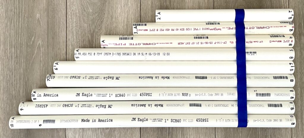
Figure 1 – Calibration Rods
Mass
(kg)
Length
(cm)
Swingweight
(kg·cm²)
0.00
0.1617534.72625.21
0.2047140.60050.07
0.2451748.882100.23
0.2626055.422149.89
0.2828160.522202.74
0.3231762.390250.37
0.3418765.86303.71
0.3578268.88355.61
0.3705271.27400.75
Table A – Calibration Rods

With an SW1, I took measurements empty and with each of the calibration rods. PVC pipe is not perfectly homogenous, so I measured each rod in both orientations. For each configuration, I recorded the oscillation period of five measurements and averaged the results. These results are summarized in Table B.

Swingweight
(kg·cm²)
Period A
(s)
Period B
(s)
Avg. Period
(s)
0.000.174970.17497
25.210.390430.390050.39024
50.070.522190.522240.52222
100.230.718420.718420.71842
149.890.870200.870300.87025
202.741.008401.006271.00734
250.371.116241.116811.11653
303.711.227931.226351.22714
355.611.323781.328151.32597
400.751.406481.406191.40634
Table B – Periods of Oscillation for Each Calibration Rod

For an oscillating, horizontal spring pendulum as used by the SW1 and most other swingweight machines, the moment of inertia of the system (racket plus oscillating portion of the machine) is proportional to the square of the oscillation period. Figure 2 is a plot of swingweight versus the square of the oscillation period. A linear trend line fits very well. For the curious, the slope and y-intercept of this line are the calibration results displayed at the bottom of the Calibrate page in the app. However, the line is fitted exactly through points at the two calibration values (around 150 and 300 kg·cm²), and the sign of the y-intercept is flipped.
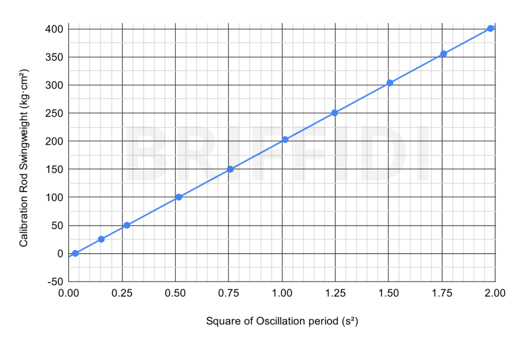
Figure 2 – Swingweight by Square of Oscillation Period

Looking much more closely, Figure 3 shows the deviation of the measured swingweight from the calculated swingweight of each calibration rod. The results of the fitted trend line in Figure 2 are used to calculate the swingweight from the period of oscillation. The first thing to notice is that the largest deviation is only 0.21 kg·cm². Second, the deviation doesn’t look entirely random. I would need to repeat this testing to see if this pattern persists. If it isn’t random, perhaps friction is causing the deviation to increase near zero. I’m not sure what else would cause such a pattern, but please leave a comment below if you have an idea.
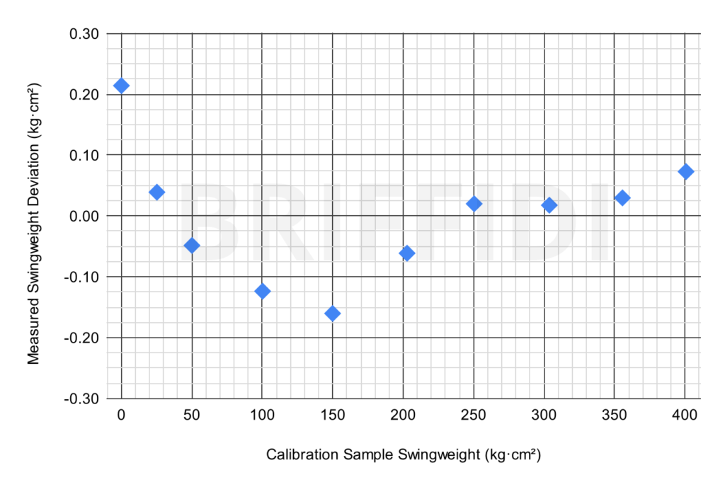
Figure 3 – Deviation by Calibration Rod

When designing the SW1, I calculated the torque deviation introduced by using a linear spring to drive a rotating pendulum. I considered other designs, such as a spiral spring or using a drum and cables to convert linear spring force into torque. In the end, I chose to stick with a simple spring drive but oscillate through a smaller arc than other swingweight machines I’ve seen, as this kept the deviation below 1% at the extremes of travel.

How do these results compare to other swingweight machines? The only similar data I’ve been able to find is from an old Babolat RDC, and it was quite non-linear. I expect that modern machines are better, but I don’t know. I’d be happy to test that. If you’re in the DFW area and have another swingweight machine that I could use for testing, please send me a message at support@briffidi.com.

So, what did I learn?

  • The SW1 is very linear from zero to 400 kg·cm² and presumably beyond.
  • It’s capable of measuring twistweight very precisely and accurately with the adapter I’m developing.
  • It’s suitable for measuring pickleball paddles (with a suitable adapter for mounting the paddle).
  • It’s reasonable to calibrate the SW1 with a single calibration object. Did you lose the calibration weight for your SW1? I can replace it, but you could also set the calibration “Object #1” value to zero and take measurements for the first and last groups with only your phone in the cradle. Absolute accuracy may suffer slightly, but using these data and calibrating with the zero and 149.89 kg·cm² measurements, the deviation at 400.75 kg·cm² is still only 0.86 kg·cm².

Posted on 5 Comments

Briffidi SW1 Android App Open Beta

1-NOV-2022 UPDATE: The Android app is out of beta. I have published updated Getting Started videos, and I’ve not received any reports of incompatibility (except virtual gyroscope sensors).

I’m pleased to announce that the Briffidi SW1 Android app is available in open beta. You can join the beta and then download the app from the Google Play Store.

Device Requirements

  • Android 8.1 (Oreo) or later
  • NFC capability
  • a physical (not virtual) gyroscope sensor (see Gyroscope Sensors)
  • a shape/size that fits securely in the cradle of the SW1 (see Physical Size/Shape)

Differences from the iOS App

  • To add your SW1 to the app, just scan the NFC tag under the Briffidi decal. There’s no need to navigate to the device page in settings and tap an “Add Device” button.
  • To delete a measurement or measurement group, long-press it and confirm instead of swiping it to the left.
  • The main button on the Measure tab displays “Place in Cradle” and is disabled until after the phone is in the mounted position.

Tested Phones

  • Google Pixel (original): Working
  • Google Pixel XL (original): Working
  • Google Pixel 6a: Working
  • Google Pixel 6 Pro: Working
  • Huawei Mate 20 Pro: Working
  • Samsung Galaxy Note 20: Working
  • Samsung Galaxy S20 FE: Working
  • Samsung Galaxy S21 Ultra: Working
  • Xiaomi Mi 10 5G: Working
  • Xiaomi Mi 10 Pro 5G: Working
  • Xiaomi Redmi Note 9: Not Working (virtual gyroscope)

If you try another phone, please leave a comment below or send a note to support@briffidi.com to tell me how it works. I’ll update this list as I hear from people.

NFC Scanning

The NFC reader in an iPhone is located at the top of the phone, so it’s easy to scan the NFC tag on the SW1. Many Android phones have the NFC reader located further down. You may need to lift the SW1 to gain sufficient access to the NFC tag. Because of this, I suggest scanning the tag before leveling the SW1.

Some Android phones have NFC scanning disabled by default. If you have trouble scanning, make sure that NFC is enabled.

It’s not necessary to scan the NFC tag except during initial setup. If it is easy to scan with your phone, you can scan it to open the app (and select the scanned device if you use more than one SW1)

Gyroscope Sensors

Some lower-end Android phones provide gyroscope capabilities via a virtual gyroscope. One tester who tried using the app on a device with a virtual gyroscope reported poor results.

There are apps, such as Gyroscope Test, that will provide details about the gyroscope sensor in your phone. If it reports the gyroscope as “virtual_gyro” or something similar, the app probably won’t work.

I also show a way to test the gyroscope using the app in the video at the top of the page.

Physical Size/Shape

Android phones come in many shapes and sizes. The SW1 was originally designed for the iPhone, which has typical size and shape. The phone-holding features of the SW1 cradle are able to accommodate most but not all phones. The phone must be secure in the cradle for accurate measurements.

Posted on 2 Comments

Racket Twistweight from Spinweight and Swingweight

A commenter recently asked on the Effect of Orientation post whether twistweight is really equal to the difference between spinweight and swingweight. It’s a common approximation based on the perpendicular axis theorem. That theorem is valid for planar (two-dimensional) objects. A tennis racket is nearly planar, but as mass deviates from that plane, twistweight will increase slightly.

To quantify the error, I looked back at the CAD model I had created for the Effect of Orientation post.

Here are the moment of inertia properties from CAD:

  • Swingweight: 306.82 kg·cm²
  • Spinweight: 320.01 kg·cm²
  • Twistweight: 13.58 kg·cm²

The difference between spinweight and swingweight is 320.01 – 306.82 = 13.19 kg·cm². The twistweight is 13.58 kg·cm², so there is an error of -0.39 kg·cm² or -2.9%. As expected, the actual twistweight is higher than approximated. This error will vary based on the accuracy of my CAD model and the geometry of the racket, but it should be somewhat close to that value.

I have a prototype device to measure twistweight more directly (UPDATE: The Twistweight Adapter is available.), as I’ve found a practical issue with determining it from spinweight and swingweight. That issue is a crooked butt cap. When I measure the swingweight of a racket and then flip it 180° and re-measure it, the measured value is often different by tenths of a kg·cm². That’s a small difference in terms of swingweight, but it’s large relative to twistweight determination.

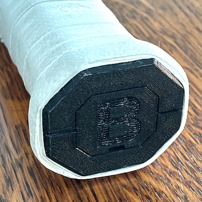
I also have been 3D printing pallets with integrated caps. As seen in the photo, the pallet is two pieces, so the face of the butt end should be nearly perfectly square in the wider direction (affecting swingweight) and perhaps not quite square in the shorter direction (affecting spinweight) if the two halves aren’t perfectly aligned. The door is slightly recessed, so it won’t interfere with measurements.

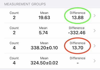
I measured the racket in the photo using both methods on my SW1. In the first (bottom) measurement group, I measured the swingweight of the racket twice in one orientation and twice at 180°. In the second group, I measured spinweight in the same way. As expected, there was a bit of deviation in the spinweight measurement, likely due to misalignment of the pallet halves. The difference of 13.70 kg·cm² is circled in red. Then, I measured my twistweight device empty and finally with the racket. The more directly measured twistweight of 13.88 kg·cm² is circled in green.

In this sample measurement, there was less difference between the two methods than there was in CAD. I haven’t explored why. There is error in all the measurements, and I haven’t used the prototype twistweight device enough to fully understand its capabilities.

So, back to the original question: is twistweight really the difference between spinweight and swingweight? Not exactly, but it’s a pretty good approximation. Practically, as long as the butt cap of the racquet is square, it’s useful, especially when the goal is to match the twistweight of similar rackets.

Thanks for the question, Ryan.

Posted on 4 Comments

Effect of Orientation Error on Racket Swingweight Measurement

A customer with an SW1 recently asked if it matters whether the racket is oriented with the head perfectly vertical, for swingweight, or perfectly horizontal, for spinweight measurements. I suspected that the result wouldn’t be very sensitive, but I wanted to quantify it.

I modeled a racket in CAD and adjusted the material densities to get a string bed of 17 grams and overall mass properties close to a typical tennis racket:

  • Mass: 333.5 grams
  • Balance: 33.2 cm
  • Swingweight: 306.8 kg·cm²
  • Twistweight: 13.6 kg·cm²

Then, I twisted it in 1° increments and output the moment of inertia about the swingweight axis:

Twist (°)Swingweight (kg·cm²)Difference (kg·cm²)
306.82
306.82+0.00
306.83+0.01
306.85+0.03
306.88+0.06
306.92+0.10
306.96+0.14
307.01+0.19
307.07+0.25
307.14+0.32
10°307.21+0.39

From the data, it seems unnecessary to be extremely accurate with racket orientation for typical swingweight measurements. At 5° of twist, which is easy to see, the swingweight result is only off 0.1 kg·cm². However, if measuring swingweight and spinweight to determine twistweight from the difference, orientation accuracy is more important. An error of 0.1 kg·cm² is more significant relative to the magnitude of twistweight.

These results should be valid for any swingweight measurement method.

If you have any questions about the SW1 or racquet measurement, leave a comment below.